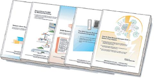
Check out our White Paper Series!
A complete library of helpful advice and survival guides for every aspect of system monitoring and control.
1-800-693-0351
Have a specific question? Ask our team of expert engineers and get a specific answer!
Sign up for the next DPS Factory Training!
Whether you're new to our equipment or you've used it for years, DPS factory training is the best way to get more from your monitoring.
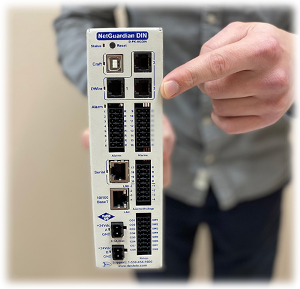
Reserve Your Seat TodayIf you have problems connecting devices together, it's always a good idea to double-check your pinouts. But sometimes the pinouts are unknown - either the pinout documentation is missing, or the port doesn't actually behave the way the documentation says it's supposed to.
In those cases, you can identify the pinout with just a little bit of detective work.
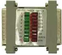
Testing pinouts is easier if you have a blinker box, a small electronic device that connects to a port and lights an LED for each pin that transmits a signal.
Note: even with a blinker box, it will still take some detective work to identify for certain the various transmit pins - for example, if you have two transmit pins, which one's DTR and which one's RTS? You can use trial and error to match each transmit pin with its corresponding receive pin on the other side, such as RTS to CTS.
Blinker boxes are convenient, but they're not absolutely necessary. You can also identify pinouts with more common tools.