Section 5: How to Test Serial Communication (202, FSK, and RS-422/RS-485) with a Butt Set

You can use a butt set as a serial port tester to listen for data as well as voice.
- When testing serial ports, you can connect an ordinary butt set to the transmit leads of the problem port. Force an alarm and listen for a series of tones.
What's going on: If you connect a phone handset to a 202, FSK or RS-422/485 line, the digital data signal will make audible sounds in the earpiece. This won't tell you anything about the quality of the data transmission … but it will tell you if there's a signal on the line.
- Do you hear any data coming from the transmit port?
- If you don't hear any data, you may have a cabling issue. Double-check the transmit port pinout.
- If you do hear data on the transmit port, clip your butt set to the transmit leads of the receive port and listen. If the receiver device is receiving information, it should also be transmitting information.
- Do you hear any data coming from the receive port?
- If you don't hear any data, double-check the RTU's address.
- If the address is OK, you may have a cabling issue. Double-check the receive port pinout.
- If you believe that the pinouts are OK, and data is being transmitted at both ends, but the connection still isn't working correctly, double-check the configuration of both the transmitter and receiver device.
Section 6: Intermittent Polling on 202 and FSK Lines
- Bad connections on FSK or 202 lines may be caused by decibel levels that are set too low or too high. Connect a VF meter to the line and adjust the signal level.
- If there is no level problem, the bad polling is most likely caused by a wiring problem.
- When you're troubleshooting wiring, the first question to ask is "Is the wiring new or old?"
- If the wiring is new, check for pinched wires, broken wires, bad soldering and pinout errors.
- If the wiring is old and it was working well before, check if anything has changed. Has anyone moved anything? Has anyone cleaned up any wiring?
Section 7: How to Identify Pinouts, with or without a Blinker Box
If you have problems connecting devices together, it's always a good idea to double-check your pinouts. But sometimes the pinouts are unknown - either the pinout documentation is missing, or the port doesn't actually behave the way the documentation says it's supposed to.
In those cases, you can identify the pinout with just a little bit of detective work.
Section 7a: Identify Pinouts with a Blinker Box
A blinker box is a great convenience for detecing pinouts.
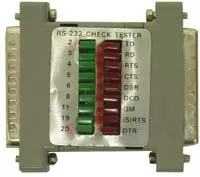
Testing pinouts is easier if you have a blinker box, a small electronic device that connects to a port and lights an LED for each pin that transmits a signal.
- Most blinker boxes only light LEDs for pins that transmit data. For RS-232 ports, these are TXD, DTR and RTS. However, some blinker boxes will light green for transmit pins and red for idle and receive pins.
- Plug your blinker box into the near-end port of the problem connection and write down the status of the LEDs.
- Then plug the blinker box into the far-end port and double-check the LED status there.
Note: even with a blinker box, it will still take some detective work to identify for certain the various transmit pins - for example, if you have two transmit pins, which one's DTR and which one's RTS? You can use trial and error to match each transmit pin with its corresponding receive pin on the other side, such as RTS to CTS.
- You may find that the near-end and far-end pinouts don't agree. But now that you've identified the real pinouts, you have a guide for rebuilding your cables.
Blinker boxes are convenient, but they're not absolutely necessary. You can also identify pinouts with more common tools.
Section 7b: Identify 202, FSK and RS-422/485 Pinouts with a Butt Set
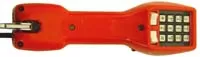
What is a Butt Set?
A Butt Set is a tool used by linemen to test phone lines. Similar to a handset on a residential telephone, the Butt Set features an outgoing mouth piece and an incoming receiver piece for two way communication. Most Butt Sets all so feature a 12 button keypad and a few various other features.
The purpose of the Butt Set is to allow Linemen to tap onto a phone line to ensure it is working properly. To do this, the Butt Set will also have two cables, while some sort of alligator clip, to attach to the line. While it may have an odd, even silly, name, the Butt Set is a critical piece of testing equipment for linemen.
If you're working with a 202, FSK or RS-422/285 connection, you can use a butt set to identify transmit pins.
- Connect your butt set to the pin you want to identify.
- If it's a transmit pin, you'll hear a series of tones in the earpiece.
- For more information on testing ports with a butt set, see Section 5, "How to Test RS-422 and RS-485 Connections with a Butt Set."
Why Would you Need to Identify Pinouts with a Butt Set?
If you are using a Butt Set to identify pinouts, you are most likely trying to connect to legacy gear.
Section 7c: Identify Serial Device Pinouts with a PC
If you're having problems connecting to a device through a serial cable, you can use a PC HyperTerminal connection to identify its pinouts.
- Connect the COM port of your PC to the serial device's port and try establishing a HyperTerminal connection.
- If you can connect via HyperTerminal, you know the device can connect to a standard PC COM port.
- Since all PC COM ports have the same standard pinout, you have a reference for identifying the pinout of the serial device's pinout. (See Figure 1 for a standard COM port pinout.)
- Note: Your connection problems may also be caused by an incorrect baud rate. If you can successfully connect via HyperTerminal, check your PC's baud rate and apply it to all equipment that connects to this device.
- Note: Your serial device may require handshaking signals. If you can successfully connect via Hyperterminal, check to make sure that all equipment that connects to your serial device supports handshaking.
- If you can't connect via HyperTerminal, the serial device's port may be broken.