Check out our White Paper Series!
A complete library of helpful advice and survival guides for every aspect of system monitoring and control.
1-800-693-0351
Have a specific question? Ask our team of expert engineers and get a specific answer!
Sign up for the next DPS Factory Training!
Whether you're new to our equipment or you've used it for years, DPS factory training is the best way to get more from your monitoring.
Reserve Your Seat TodayCurrent sensors are devices that allow you to measure the current passing through a wire by using the magnetic field to detect and generate a proportional output. With these sensors, you can measure current passively, without interrupting the circuit in any way. Also, they can be used for both AC and DC current.
There are a variety of applications for current sensors. They can be used, for example, for power metering, control system diagnosis, current supply measurement, and monitoring of rechargeable batteries.
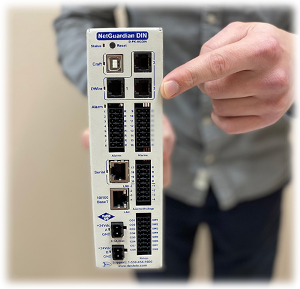
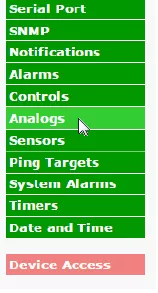
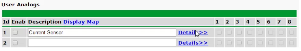
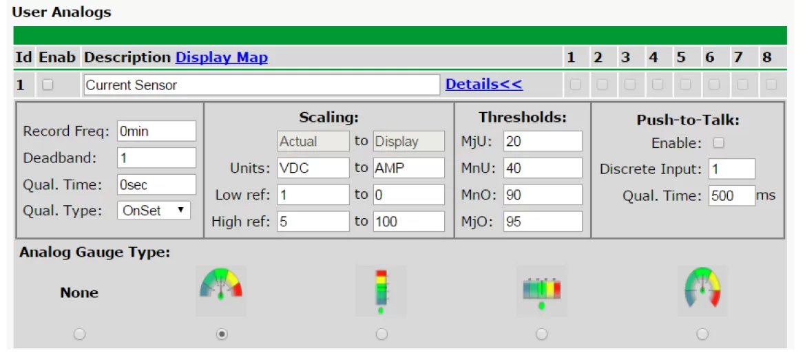
If you have one of our NetGuardian RTUs, you can configure sensors to have the capability to monitor current. In this article, we'll dive into how you can properly wire and configure current sensors using your NetGuardian.
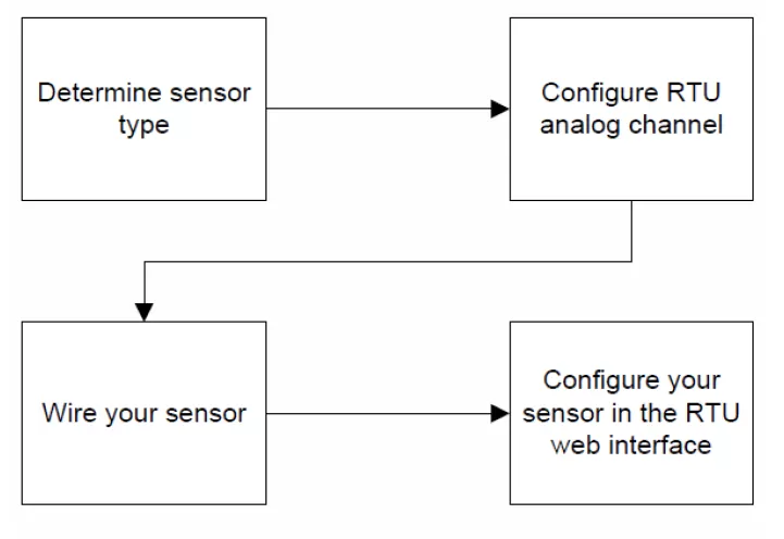
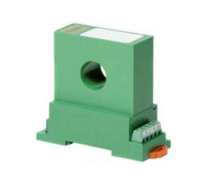
For the purposes of this article, we'll explain how to set up and configure four different sensors provided by DPS. So, first of all, you need to determine what kind of sensor you are using. Here are some options:
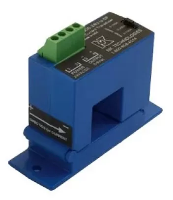


For the D-PK-SENSR-12015: apply hardware shunt to configure channel for 4-20mA (current mode) operation. Typically, there is a hatch panel on the unit to access the shunt.
For the other sensors: remove hardware shunt to configure channel for voltage mode. The unit ships in voltage mode by default.
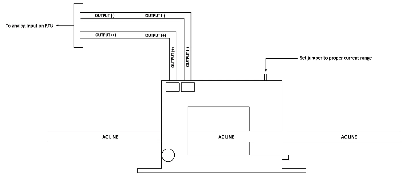
D-PK-SENSR-12015 wiring
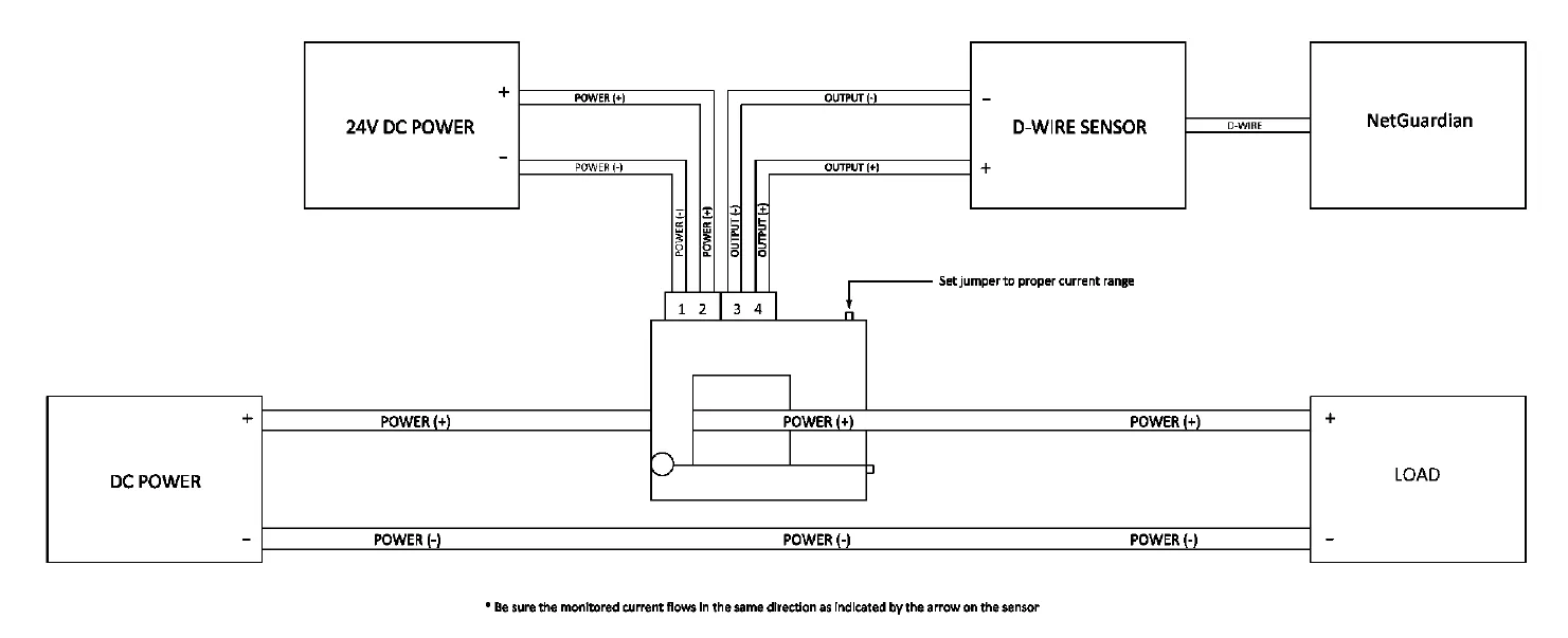
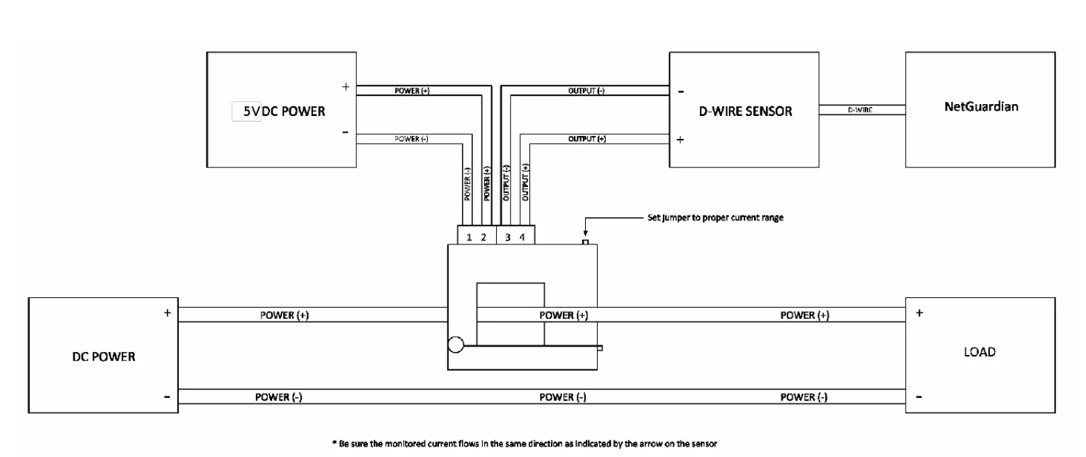
D-PK-SENSR-12092 wiring
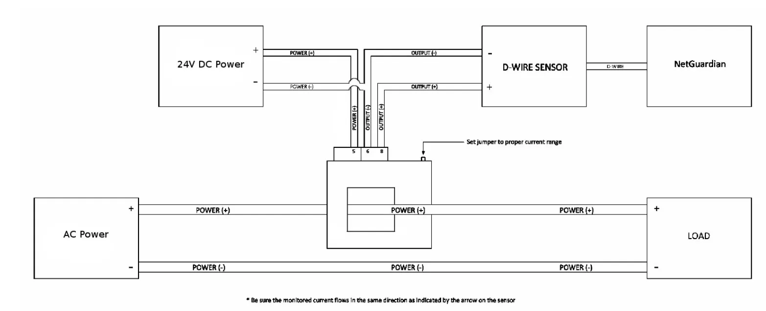
D-PK-SENSR-12140 wiring
D-PK-SENSR-12196 wiring
Once the sensor is connected, setting it up on the RTU will be the same process.
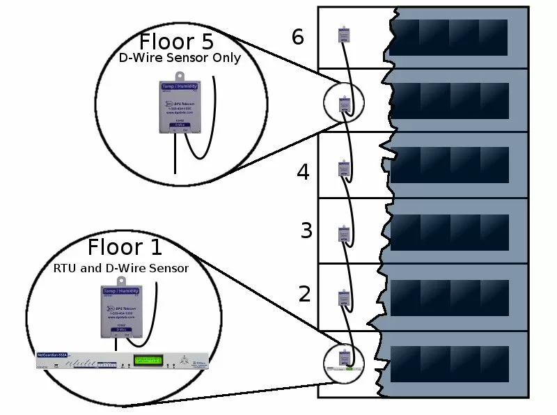
If you didn't deploy your current monitoring solution yet, then it's important that you explore all your alternatives before investing in anything. One example of an efficient monitoring system is pairing the NetGuardian 832A G5 RTU with the D-Wire sensors.
The NetGuardian 832A G5 is a powerful RTU that has the capacity for 32 discrete alarm points, 8 analog inputs, and 8 control relays. All these features are maximized by the 832A's advanced hardware, high-speed processor, and enhanced security options.
To monitor current, all you need to do is plug a D-Wire sensor into one of the 832A's ports and your RTU will gain this capability. There are many different types of D-Wire sensors, each of them designed to give your RTU monitoring functions that otherwise it wouldn't have.
All you need is a common RJ-12 cable to link your sensor to your RTU. This same cable will provide both data and power from the NetGuardian to the D-Wire sensor. Also, to lessen the number of cables and conserve ports on your RTU, you can daisy-chain up to 16 D-Wire sensors through one port.
In a nutshell, the NetGuardian 832A G5 is a powerful RTU that will be able to handle all your network needs. When paired with D-Wire sensors, you'll be achieving a cost-effective way to increase your unit's capacity and monitor whatever applications you have - saving you both time and money.
Wiring and configuring your current sensor to your existing NetGuardian RTU is simple and easy. But, you encounter any issues, feel free to contact our tech support. Our experts can help you with any problems you might be experiencing.
Learn more about battery monitoring - download the Battery Voltage Monitoring White Paper.
Also, if you need a monitoring system, but still is in the process of evaluating your options, reach out to us. With in-house engineering and manufacturing, we offer custom products to match your exact specs - giving you a perfect-fit monitoring solution. Contact us today and learn more about how we can help you monitor your specific application.

Morgana Siggins
Morgana Siggins is a marketing writer, content creator, and documentation specialist at DPS Telecom. She has created over 200 blog articles and videos sharing her years of experience in the remote monitoring industry.