Download our free SCADA tutorial.
An introduction to SCADA from your own perspective.
1-800-693-0351
Have a specific question? Ask our team of expert engineers and get a specific answer!
Sign up for the next DPS Factory Training!
Whether you're new to our equipment or you've used it for years, DPS factory training is the best way to get more from your monitoring.
Reserve Your Seat Today
Let's walk through how to connect your alarm points to a 66-Block and where to find user manuals for all the DPS products.

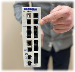
The 50-pin amphenol connector manages the alarm status for all the 20 discretes inputs and the 4 control relays outputs on the NetGuardian 420. This amphenol will link your NetGuardian to the 66-Block. You'll find the amphenol on the back of the NetGuardian.
Keep in mind, when attaching the NetGuardian and 66-Block together, that the 66-Block numbering begins from the top. The count starts from the 1 pin and 26 pin. Since the pins are next to each other, you'll count in pairs. The order, then, is: 1 pin - 26 pin, 2 pin - 27 pin, 3 pin - 28 pin and so on.
There are several different settings in every NetGuardian user manual. So, for this case, what you want to check out is the hardware portion in the manual for your specific NetGuardian.
In the NetGuardian 420 User Manual, you can see that we have the exact pins for each of the alarm points and controls.
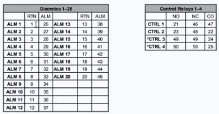
For the discretes you'll have to look for the alarm points 1 through 20 - they'll have a return pin on pins 1 through 20 and alarm pins on 26 through 45. Remember, though, that they are right next to each other due to the 66-Block numbering that starts with 1-26 at the top, following 2-27, etc.
For the control relays 1 and 2, we’ll switch from the pair scheme to something a little bit different. Observe that we have a normally open pin (NO), a normally closed pin (NC) and a common pin (CO). So, if you want your relay to behave with normally open or normally closed behavior - you'll want to choose either the normally open or the common pin; if you want a normally closed behavior – and you'll have to choose the normally closed and the common pin.
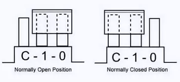
Note that, on the control relays 3 and 4, NO and NC are the same. So, what's going on behind the scenes is that this normally open - normally closed behavior is determined by a shunt. We can find more about this on the section 5.10 Controls of the NetGuardian 420 user manual. Basically, you'll need to move the shunt over from the normally open position to a normally closed position to get that to work properly, depending on whether you want a normally open or a normally closed configuration. By default, these are always going to be sent to you in a normally open position.
There's a few more interesting points that we can look at for hardware pinouts. The user manual brings a description of all the pins, the pin numbering and the pin color codes for your 66-Block. Therefore, this is a good guide if you're looking for extra information on exactly where these pins are going to be connected, and where they're going to be returning to, and what their function is.
If you’ve misplaced the physical copy of the manual that you were sent, you can access www.dpstele.com. At the top right-hand corner of the web page, hit the support tab. This will take you to the Download User Manuals link. This link will allow you to download any user manual at any time.