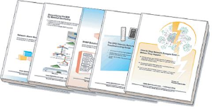
Check out our White Paper Series!
A complete library of helpful advice and survival guides for every aspect of system monitoring and control.
1-800-693-0351
Have a specific question? Ask our team of expert engineers and get a specific answer!
Sign up for the next DPS Factory Training!
Whether you're new to our equipment or you've used it for years, DPS factory training is the best way to get more from your monitoring.
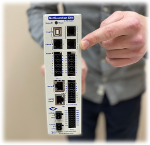
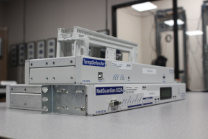
Reserve Your Seat TodayI just visited a major supplier of complex telecom systems. Our TempDefender G2 is part of a solution currently being built, and our client was reporting some strange electrical issues over the phone.
This project revolves around current transducers to monitor two DC power feeds.
The following components are part of this project:
The first unusual symptom that eventually got me to board a plane for a site visit was repeated blowing of 500mA fuses on our DC-to-DC converters. Current transducers have a max power draw of 80mA each, so a pair should peak at no more than 160mA at maximum power consumption. This was obviously very strange.
We were not able to ever replicate this symptom in our lab. The voltage converters operated perfectly at our factory. It was at this point that we decided to send a team to investigate
We know how important site visits can be for both discussions and technical investigations like this one. That's why we work hard to spread our travel costs out across as many visits as possible. This makes it possible to visit you even more often than we otherwise could.
I was scheduled to attend the PowerGen trade show in Orlando. The show ran Tues-Thurs, presenting a great opportunity to visit this client within a few weeks of the initial problem report.
I flew from the Digitize offices in New Jersey where I've been working for the last 8 months, largely on DPS Telecom projects. I was joined by Ty, an engineer who flew from our headquarters in Fresno, CA.
On Monday, we made our way to our client's office to investigate the strange problem with fuses repeatedly blowing.
Being the DPS engineer based at DPS HQ, Ty brought with him a wide range of equipment that probably or might be useful during troubleshooting. We brought different product variations on the DC-to-DC converter.
We also brought 1A "slow-blow" fuses that might perhaps alleviate the problem with blown fuses. "Slow-blow" is a fuse property that indicates the fuse can take a larger in-rush current before blowing. It will still blow to protect the device if the 1A rating is exceeded for very long, but brief moments of higher current (such as when a device is powered on) will not blow the fuse.
The 1A slow-blow fuses proved themselves on a test rack and in our client's full-fledged simulation lab. We were glad to make progress, but we were still perplexed by why there would ever be a problem in the first place.
Knowing that "fuzzy thinking" will eventually come back to bite both DPS and our client, we pressed on with our investigation. What we found was fairly unusual.
Although I'm not an electrical engineer by training, I know how to troubleshoot things. I knew we'd find the true source of this problem.
We started by taking a look at the readings coming from the transducer. They were oddly very high. In a site where the expected current draw was about 11A at that time, we saw a reading of about 90A. This was truly bizarre.
I started troubleshooting by having Ty use a multimeter to confirm that our D-Wire node was correctly reading the transducer's output. Was it really reading 23mA when it should be reading about 6.5mA?
Sure enough, the handheld multimeter showed 38mA (this only registered as 23mA after "pegging the needle" on our D-Wire node). The D-Wire node was behaving as it should. The problem was somewhere else.
We used a handled current sensor to clip around the power cable and measure it independently. The reading was the expected 11.5A. The problem was somewhere else.
It was at this point that I started to strip away elements to see when the problem was solved. I unplugged to TempDefender RTU from LAN. I even unplugged the TempDefender's input power, causing it to go dark. The transducer was STILL reading an impossible 38mA.
I then unplugged the D-Wire cable (used for a small amount of power and data transmission) and, instantly, the transducer was outputting the correct 6.5mA (indicating about 11 VDC in a 0-75 VDC range).
There you have it. Because the D-wire nodes attached to a TempDefender share its ground through the rack, it's possible for voltage potential to flow between them. That had to be what was happening here.
After all of this troubleshooting, we were staring at the problem. Due to a difference in grounding, electricity was flowing from the transducer to the site's grounding bar.
There are two ways to solve this:
In the end, our client decided to review their site's electrical setup with the relevant supervising personnel. I also provided some instruction on the configuration options in the TempDefender's web interface, so that gave my client some useful items to work on as he prepares for the full deployment.
We're a full-service provider of remote monitoring and control systems. If you're trying to sort out your purchase options, give me a call here at DPS. I can work with you on the phone and maybe even put a site visit on the calendar.
This service continues after you buy, of course. We don't want one sale. We want a long-lasting partnership that benefits both of us.
To get started on your remote monitoring project, call DPS at 1-800-693-0351 or email us at sales@dpstele.com

Andrew Erickson
Andrew Erickson is an Application Engineer at DPS Telecom, a manufacturer of semi-custom remote alarm monitoring systems based in Fresno, California. Andrew brings more than 19 years of experience building site monitoring solutions, developing intuitive user interfaces and documentation, and opt...