Check out our White Paper Series!
A complete library of helpful advice and survival guides for every aspect of system monitoring and control.
1-800-693-0351
Have a specific question? Ask our team of expert engineers and get a specific answer!
Sign up for the next DPS Factory Training!
Whether you're new to our equipment or you've used it for years, DPS factory training is the best way to get more from your monitoring.
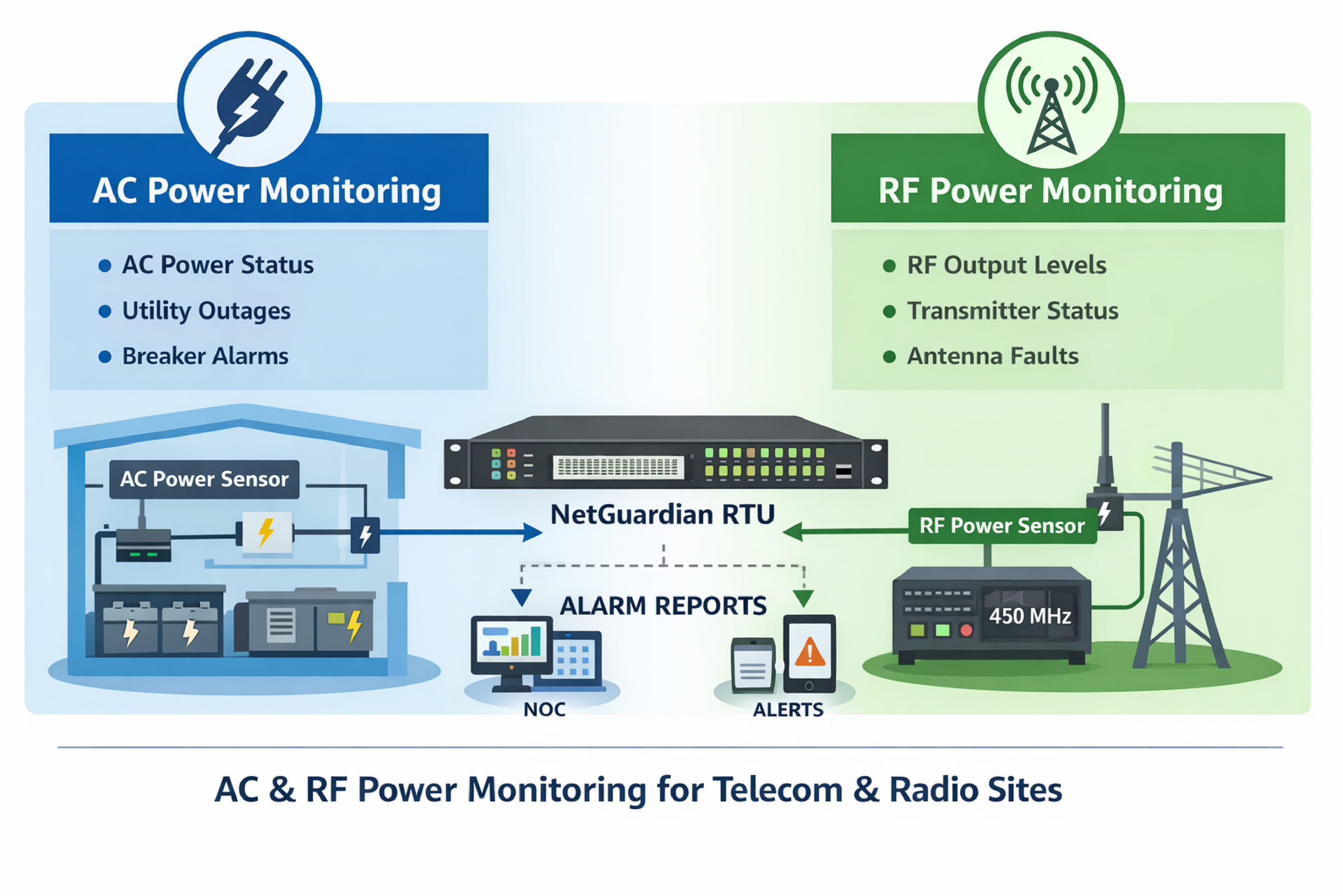
Reserve Your Seat TodayIn infrastructure monitoring, AC and RF power monitoring refers to measuring two different but related conditions at remote communications sites: (1) whether an AC power circuit is present and within expected limits, and (2) whether a radio transmitter is producing the expected RF output power. Together, these measurements help operations teams detect power failures, transmitter faults, and degraded coverage before they become extended outages.
AC power out monitoring means detecting the loss (or abnormal state) of an AC feed that powers mission-critical equipment. In many remote cabinets, shelters, and transmitter huts, AC mains availability is the first dependency for battery chargers, rectifiers, HVAC, and other supporting systems.
AC power monitoring is typically implemented as a discrete alarm input at the RTU. When the AC source is present, the input is in a normal state. When AC is lost (or drops below a threshold), the input changes state and the RTU generates an alarm for the NOC or maintenance staff.
Common operational reasons to monitor AC circuits include:
An AC power out alert sensor is a device that converts the presence of an AC voltage into a safe alarm signal that an RTU can read. The key concept is isolation and level conversion: the AC circuit itself should not be wired directly into an RTU alarm input.
In a typical design, the sensor monitors the AC circuit and provides a dry contact or a logic-level output to the RTU. The RTU treats that output as a discrete input alarm and can generate local annunciation and remote notifications.
For teams building a repeatable bill of materials, DPS Telecom offers an AC Power Out Alert Sensor with part number D-PR-592-10A-00. In many deployments, this is used to monitor one or more AC circuits feeding site power equipment, with the alarm inputs landing on a NetGuardian RTU.
Implementation details that matter during design and commissioning include:
RF power monitoring means measuring the transmitter output power level on a radio frequency path and alarming when power is too low, too high, or absent. In infrastructure monitoring, RF power is commonly monitored to detect failed transmitters, PA degradation, coax problems, antenna faults, or misconfigured equipment.
When a system owner operates multiple transmitters at a site, RF power monitoring is often implemented per transmitter. That design supports faster fault isolation because the NOC can see exactly which channel or carrier is affected.
RF monitoring is especially relevant for UHF systems in the 450 MHz range, where an apparent "site up" condition can still hide partial service loss if only one transmitter is underperforming. Measuring RF output adds visibility that pure network reachability checks cannot provide.
An RF power sensor specification defines the measurement point, physical interface, and alarm outputs that will integrate with an RTU. The goal is to ensure the sensor can be installed inline (or via coupler) and produce a reliable signal for alarming.
Specifications that are commonly clarified during procurement include:
For a site monitoring five transmitters, a common approach is to use five RF sensing points so each transmitter has its own measurement and alarm identity in the RTU configuration.
Multi-point site monitoring means using a single RTU to aggregate many independent alarm and measurement channels. A practical design starts with an I/O map: every transmitter RF status, every AC circuit status, and any additional needs like door, temperature, and battery conditions.
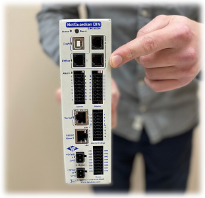
A NetGuardian RTU is typically selected based on:
In many standard monitoring architectures, one RTU can handle multiple transmitters and power circuits, provided the sensor outputs are compatible and the I/O count is sized correctly. This design reduces the number of IP endpoints and centralizes site alarming and event logging.
A bill of materials (BOM) is the structured list that ties the monitoring intent to actual parts. Even for a relatively small site, writing the BOM explicitly helps avoid field rework and last-minute substitutions.
| Monitoring Need | Typical Approach | Notes For Design Review |
|---|---|---|
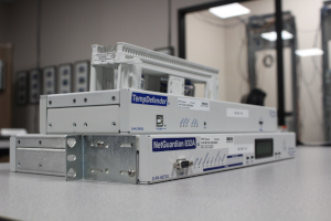
| RTU for alarm collection and reporting | NetGuardian RTU (example: NetGuardian 832A) | Confirm I/O count, protocol requirements, and power input build option. |
| Monitor two AC circuits | Two AC Power Out Alert Sensors | Decide which circuits to monitor: utility feed, UPS output, or specific branch circuits. |
| Monitor five UHF transmitters | Five RF power sensing points | Specify frequency band, expected power, connector type (often N-type), and output format. |
| Wiring and labeling | Terminal blocks, labels, and documentation set | Alarm naming should match panel labels and transmitter IDs used by operations. |
| Central alarming (optional) | Alarm master platform such as T/Mon | Use when consolidating alarms from many sites and many protocols into one operator view. |
This structure supports either direct alarming from the RTU to your monitoring stack or aggregation through an alarm master, depending on the scale of the network and how standardized the NOC workflow needs to be.
RTU power selection refers to the input power type used to run the monitoring device itself, not the power being monitored. In field deployments, matching the RTU power input to available site power can simplify installation and improve resiliency.
Common considerations include:
When requesting a configuration, it is typical to specify the preferred RTU input power (for example, 12 VDC when available) and identify an acceptable fallback (for example, 120 VAC when DC is not available).
Alarm reporting is the method an RTU uses to deliver events from the site to operators. In infrastructure monitoring, an alarm is most actionable when it is timely, correctly categorized, and routed to the correct workflow.
Common reporting patterns include:
For reseller and integrator use cases, standardized alarming is often as important as the hardware. Consistent point naming and consistent severities reduce commissioning time on each new site.
Commissioning is defined as the process of validating wiring, sensor behavior, and alarm reporting end-to-end before a system is put into service. A commissioning plan reduces nuisance alarms and avoids situations where an operator receives an alarm but cannot interpret it.
A practical commissioning sequence for a combined AC and RF monitoring deployment is:
If the deployment includes an alarm master such as T/Mon, commissioning should also validate that the central console displays the correct site, device, and point names, and that escalation rules match operations policy.
Failure mode coverage is the list of problems a monitoring design can detect quickly and unambiguously. AC and RF monitoring points are often chosen because they cover both facility-layer and service-layer failures.
Common failure modes detected by AC power out monitoring include:
Common failure modes detected by RF power monitoring include:
For operations teams, the value is not only detection but faster triage. Knowing that AC is present but RF is low points toward transmitter chain troubleshooting. Knowing AC is out points toward site power restoration workflows.
Standardized integration refers to building a repeatable monitoring package that can be deployed across many sites and customers with minimal variation. For integrators and resellers, the main goal is to reduce engineering time per site while maintaining correct sensor selection and clean alarm mapping.
Best practices that tend to reduce surprises include:
DPS Telecom commonly supports these standardized approaches with NetGuardian RTUs for site-level I/O and with T/Mon for centralized alarm presentation when networks grow beyond a handful of sites.
Yes. A single RTU can typically monitor multiple discrete alarm points (such as AC power present) and multiple RF-related points, depending on whether the RF sensor provides discrete outputs, analog outputs, or both and whether the RTU has sufficient I/O capacity.
Provide the operating frequency range, expected power levels, preferred connector type (often N-type), whether forward-only or forward-plus-reflected power is needed, and how the sensor output should interface to the RTU.
It depends on what is reliably available at the site and what remains powered during a utility outage. Many operators prefer DC power so monitoring stays online through AC failures, but AC-powered configurations can work well when backed by UPS or generator.
Use appropriate thresholds and time delays to avoid alarming on brief transitions, such as key-up events. Commissioning should validate that alarms represent real service-impacting conditions, not normal transmitter behavior.
An alarm master is typically added when there are many sites, multiple alarm sources, or multiple protocols to normalize into one operator workflow. It can simplify correlation, escalation, and alarm presentation across the network.
If you are building a monitoring package for radio, public safety, utility, transportation, or telecom sites and need to combine AC power-out alarming with transmitter RF power visibility, DPS Telecom can help you select the right NetGuardian RTU build and sensor set and define a clean alarm integration plan.

Andrew Erickson
Andrew Erickson is an Application Engineer at DPS Telecom, a manufacturer of semi-custom remote alarm monitoring systems based in Fresno, California. Andrew brings more than 19 years of experience building site monitoring solutions, developing intuitive user interfaces and documentation, and opt...