Check out our White Paper Series!
A complete library of helpful advice and survival guides for every aspect of system monitoring and control.
1-800-693-0351
Have a specific question? Ask our team of expert engineers and get a specific answer!
Sign up for the next DPS Factory Training!
Whether you're new to our equipment or you've used it for years, DPS factory training is the best way to get more from your monitoring.
Reserve Your Seat TodayFor infrastructure monitoring, a segmented control architecture for roadside cabinets refers to separating power distribution from cabinet logic and telemetry so that each function remains clear, serviceable, and reliable. This approach typically uses one subsystem focused on protected power distribution and another focused on alarm reporting, environmental sensing, maintenance behaviors, and integration to an existing supervisory platform.
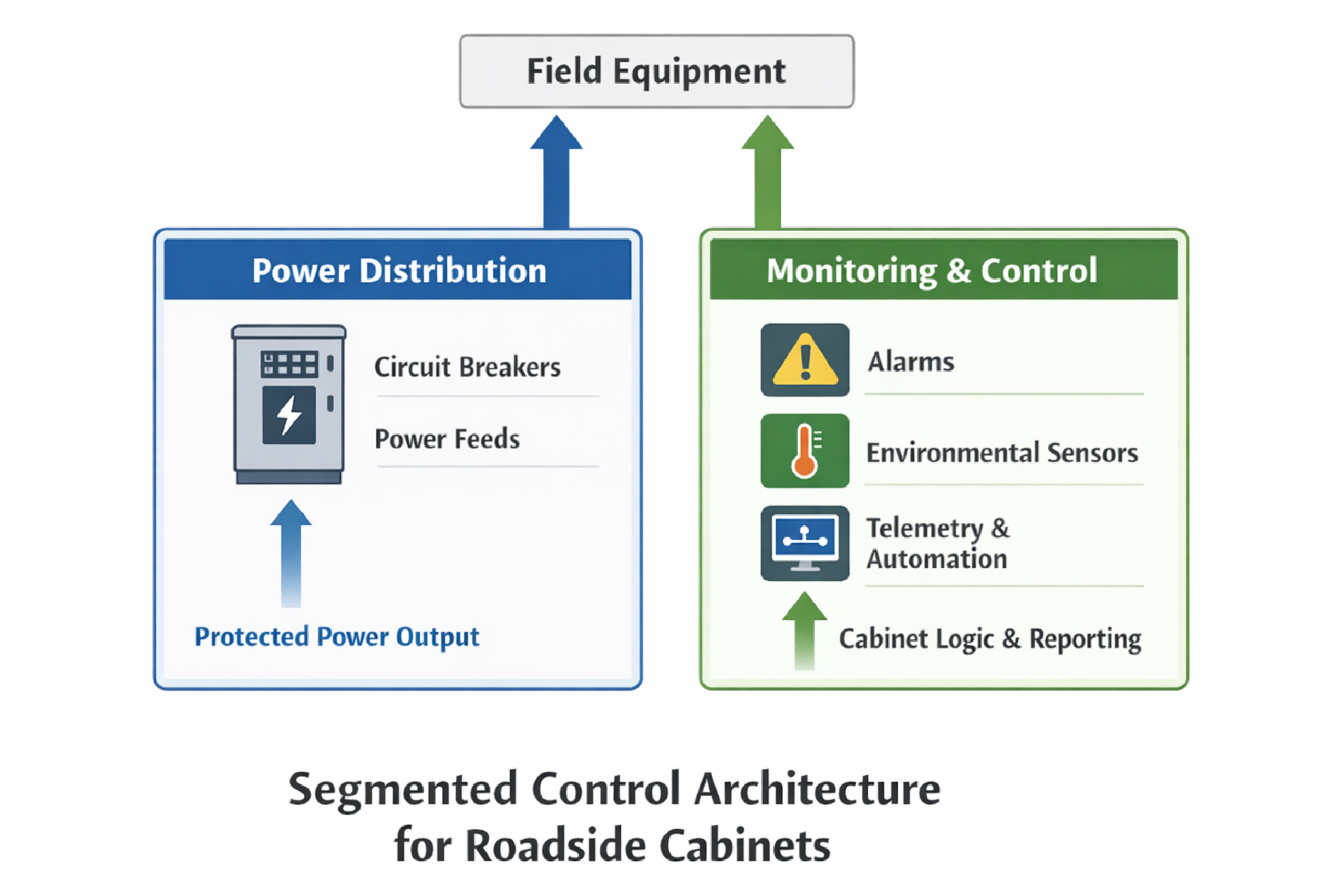
A segmented control architecture for a roadside infrastructure cabinet means using two coordinated control layers with different responsibilities. One layer focuses on distributing and protecting power to field equipment. The other focuses on cabinet intelligence, connectivity, and automation.
In many cabinets, the power distribution function must remain simple and deterministic. That is why a dedicated power distribution subsystem often handles multiple field outputs and upstream power sources.
In the same cabinet, operations teams also need an IP-enabled monitoring and control layer that can report alarms, log events, expose status through a user interface, and implement behaviors such as maintenance mode or controlled shutdown of cabinet electronics. This separation reduces confusion about where a function lives and can make procurement, testing, and maintenance easier.
Incoming power feed partitioning in a roadside cabinet means deciding which upstream circuits land in the power distribution subsystem versus the cabinet monitoring subsystem. The goal is to match circuits to the function that can best protect and observe them, while keeping wiring and commissioning predictable.
A typical requirement is multiple upstream feeds for continuity. The power distribution subsystem receives these feeds and then distributes power to field outputs through individual protective devices.
Separately, the cabinet monitoring subsystem often needs its own electronics circuits to support compute, networking, peripheral controllers, and other cabinet loads. Some designs include one guaranteed electronics feed plus additional spare inputs to support future growth or cabinet options.
Cabinet HVAC power is often treated differently. A common design choice is to allow an HVAC feed to pass through without being switched by cabinet logic. That keeps thermal management independent from monitoring logic, while still allowing the cabinet controller to observe temperatures and raise alarms.
Install-time mapping means the input-to-output relationship is physically selected during installation rather than being changed through software at runtime. In cabinet power distribution, this approach intentionally trades flexibility for clarity.
A runtime-configurable switching matrix can look attractive because it promises maximum flexibility. In practice, it can increase commissioning time and create misconfiguration risk when different technicians assume different mappings. A mapping error can appear as a power fault, controller fault, or field wiring issue, which increases time-to-repair.
Install-time mapping is deterministic. A technician can inspect the panel, verify the physical configuration, and know the mapping without needing software tools or configuration files to interpret the as-built wiring.
A simple but effective operational practice is to provide a front-panel mapping graphic that installers can mark to reflect the as-installed configuration. A marked graphic reduces the chance that a future technician assumes a default mapping that no longer matches the cabinet.
Source selection for field outputs means deciding which upstream source feeds each output. In roadside cabinets, the practical requirement is often to support multiple outputs while allowing flexibility so that critical loads can be assigned to the preferred source based on operational priorities.
An install-time, physically assignable source mapping per output lets a team prioritize which loads should stay powered under different upstream conditions. The assignment does not need to be evenly split. It should reflect which devices are most operationally important for safety and service continuity.
Visibility must also remain when one source is lost. That leads to a separate requirement: the controller electronics should be powered redundantly so that loss of one source does not also remove telemetry and alarm reporting. This is a monitoring-first design principle because operators need to know what happened during a feed failure, not lose the monitoring system at the same time.
Electrical layout choices such as protective-device placement can improve clarity. A simple example is arranging devices in an order that aligns with how technicians label and trace feeds. Small layout changes can reduce mistakes during emergency troubleshooting when time pressure is high.
Monitored cabinet protection means instrumenting both the protection devices and the load behavior so that the operations center can distinguish between a trip, a load loss, and an upstream feed issue.
Protection-event indication often requires status feedback from each protective device. Each status point can then be monitored as a discrete input so the system can report which specific output experienced a protection event.
Per-output current sensing allows the system to detect conditions such as a no-load state, a disconnected field device, or a damaged cable. Current sensing complements protection status because a protective device can remain closed even when a load is absent.
Some supervisory systems only consume a single summary alarm contact. If a summary is used, a practical technique is to re-assert the summary output when a new event occurs while the summary is already active. This creates a new transition that some external alarm receivers require for event detection. This behavior should be explicitly specified so that alarm semantics match supervisory expectations.
| Cabinet Condition | Primary Detection Method | What It Helps Operators Distinguish | Common Alarm Reporting Options |
|---|---|---|---|
| Protection event on a specific output | Protective-device status feedback to a monitored input | Protection event vs load fault | Per-point alarm, or summary contact with re-latch behavior |
| No-load or cable fault condition | Per-output current sensing | Load not drawing current even though the output is enabled | Threshold alarms, or computed status points |
| Upstream source loss | Source presence sensing | Distribution fault vs upstream power issue | Discrete alarm, event log entry, and status display |
| Repeated trips or intermittent load behavior | Event log + alarm history correlation | Recurring fault vs one-time event | Exportable event log and supervisory timestamps |
Event logging in a monitored cabinet power system means capturing a timestamped record of alarms and state changes so that operations and maintenance teams can reconstruct what happened. In field environments, event logs are often used to correlate cabinet power events to incidents, weather, planned maintenance, and upstream utility disturbances.
Many modern specifications expect substantial event capacity, along with the ability to export the data in a common file format through a web interface. The key value is operational: field and operations teams can share the same event evidence without requiring specialized tools.
At the controller level, event logging should capture at least: protection-event changes, source-status changes, summary output transitions if used, temperature alarms, and maintenance mode transitions. The log should preserve point identity so that exported records remain meaningful in ticketing and post-incident reviews.
Front-panel indication in a roadside cabinet refers to local, at-a-glance status that helps field technicians quickly determine whether power is present and where the fault likely resides. For field power distribution, highly visible indicators per output can reduce time spent probing and tracing circuits.
A practical indicator scheme is providing clear per-output power-present indication. Some designs indicate power presence on both the input and output sides of a protective device. This helps differentiate an upstream source issue from a device-open or downstream wiring issue.
Front-panel indicators can also reduce the need for features that add cost or create maintenance overhead. For example, if an IP-enabled cabinet controller already provides the user interface and status pages, a second local interface on the distribution subsystem may add little operational value. Similarly, convenience features inside powered cabinets can introduce added safety and compliance considerations, so many designs prefer a more controlled cabinet philosophy.
Graceful shutdown in a monitored cabinet means the controller can initiate an orderly shutdown of cabinet electronics when conditions require it. This can prevent file system corruption, reduce recovery time, and support safe maintenance workflows.
Two common interface options are network-based signaling and contact closure signaling. Network-based shutdown requires compatible server hardware or a management controller that can accept remote triggers. Contact-closure shutdown requires a compatible input on the server or an interface accessory that translates a relay closure into a recognized shutdown signal.
In many cabinet designs, the monitoring controller is expected to provide RTU-like I/O for cabinet logic. A common target is a moderate number of monitored inputs and control outputs to support functions such as shutdown, maintenance mode, and fallback behaviors when external systems are unavailable.
Maintenance mode is a defined operational state in which alarms are suppressed or reclassified during planned work, while critical alarms remain active. In practice, maintenance mode must be easy to enable and disable, and it must be visible to operators. A practical requirement is implementing maintenance mode as a built-in feature with configuration and control exposed through a standard user interface so that the workflow does not depend on a single commissioning tool.
Temperature monitoring in roadside cabinets is most useful when the sensor can be placed where heat problems occur, not only on the controller board. Specifications often prefer support for a remote temperature sensor so that it can be positioned near compute equipment, power supplies, or other known hot spots.
Supervisory integration means delivering cabinet alarms and status to the system that operators already use. In many environments, the alarm receiver may be a third-party platform with strict protocol constraints, and a traditional alarm master may not be the designated destination.
When the supervisory protocol is constrained, the engineering task becomes: determine the required protocol, determine the number of points supported, and map cabinet conditions into the supervisory model. Some organizations only accept a single summary alarm today, while others require detailed per-point visibility. That difference should be resolved early because it changes wiring, I/O counts, and configuration effort.
In practice, these projects often require protocol mediation and alarm integration approaches that reduce tool sprawl. When the environment allows centralized alarm aggregation, an alarm management platform can provide a unified operator view. When another supervisory system must remain the primary destination, an edge monitoring device can still act as a local collector and translator for cabinet conditions.
| Integration Approach | Best Fit When | Operational Strength | Trade-Off |
|---|---|---|---|
| Single summary alarm output | The supervisory system only accepts a basic alarm input | Simple, fast to deploy | Limited detail; requires follow-up to identify the exact fault |
| Per-point alarm reporting | The supervisory system supports multiple points and clear mapping | Faster troubleshooting and fewer ambiguous tickets | More configuration and testing effort |
| Protocol mediation at the cabinet edge | Field-device protocols and supervisory protocol do not match directly | Reduces custom development and monitoring sprawl | Requires disciplined point naming and alarm modeling |
| Central alarm aggregation | Operations wants a unified alarm console across many subsystems | Centralized visibility and escalation workflows | May not fit environments where another supervisory platform is mandatory |
Monitoring continuity means the cabinet can still report meaningful alarms during partial power failure conditions. A cabinet that goes dark when one source drops can create a blind spot precisely when operators need the most information.
A common requirement is powering controller electronics from more than one available source so visibility remains if one source is lost. The same principle applies to both the power distribution subsystem and the cabinet monitoring subsystem. If the monitoring layer has multiple supplies derived from different inputs, the design should ensure that at least one remains available across plausible source-loss scenarios.
Where cabinets are fed from larger utility panels, another practical detail is that cabinet-electronics inputs may land on different phases or branches. The commissioning plan should include validation that the expected redundancy works under realistic upstream conditions.
A practical specification for cabinet power monitoring and control should translate operational expectations into explicit, testable requirements. The goal is to prevent late-stage redesign when teams discover that the supervisory system needs a different alarm format, or that cabinet electronics cannot accept the chosen shutdown method.
A commissioning checklist for a monitored roadside cabinet is a short set of steps that validate the design assumptions in the field. The checklist should be used during factory test and repeated during on-site commissioning.
Protection-event indication reports whether a protective device has operated, typically through a status point. Current sensing reports the actual load draw, which can identify a disconnected field device even when the protective path remains closed.
Software-configurable switching can increase the risk of misconfiguration and make troubleshooting slower. Install-time physical mapping is easier to verify and reduces ambiguity for future technicians.
The required alarm point count depends on supervisory-system capabilities and operational expectations. Some teams accept a single summary alarm, while others require detailed visibility. The decision changes I/O needs and integration work.
If a supervisory system requires a state transition to recognize a new event, the summary output can be momentarily released and then re-asserted when an additional event occurs while the summary is already active. This behavior should be specified and tested.
Maintenance mode is most reliable when it is a built-in feature that can be configured and activated through a standard user interface. This reduces dependence on a single commissioning tool and supports field workflows.
If a roadside or industrial cabinet project needs clear input partitioning, deterministic output mapping, protection and current monitoring, event logging, and integration to an existing supervisory platform, a structured design and integration plan can help translate those requirements into a testable solution.

Andrew Erickson
Andrew Erickson is an Application Engineer at DPS Telecom, a manufacturer of semi-custom remote alarm monitoring systems based in Fresno, California. Andrew brings more than 19 years of experience building site monitoring solutions, developing intuitive user interfaces and documentation, and opt...