Check out our White Paper Series!
A complete library of helpful advice and survival guides for every aspect of system monitoring and control.
1-800-693-0351
Have a specific question? Ask our team of expert engineers and get a specific answer!
Sign up for the next DPS Factory Training!
Whether you're new to our equipment or you've used it for years, DPS factory training is the best way to get more from your monitoring.
Reserve Your Seat Today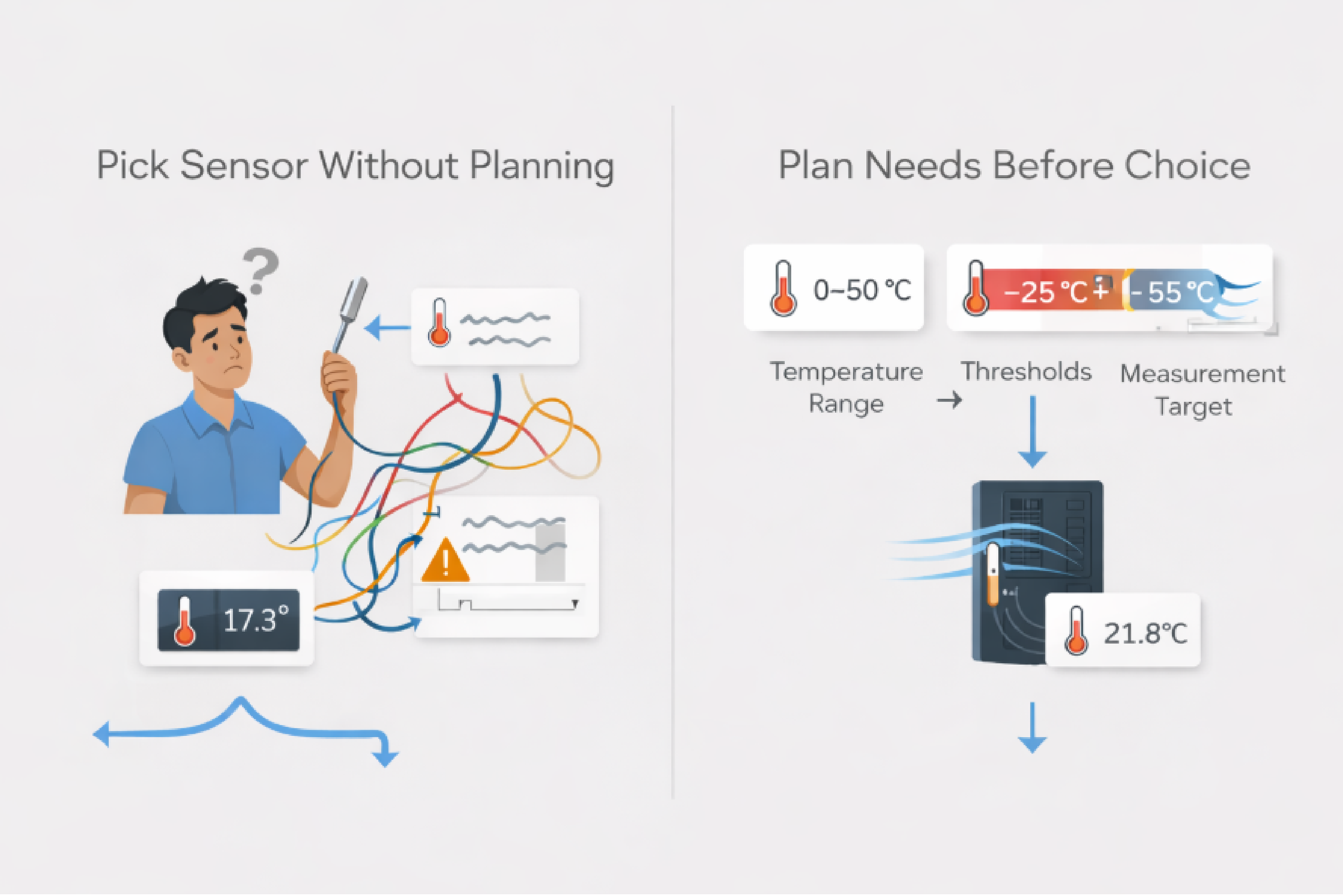
Choosing the best temperature sensor for an equipment room is fundamentally a measurement system question: Are you staying inside your equipment's thermal envelope, and will you know fast enough when you're drifting out of it?
At DPS Telecom, we've deployed temperature monitoring across more than 172,000 devices, from telecom shelters and server rooms to distributed field sites. The failures we've seen weren't caused by bad sensors. They were caused by sensors placed in the wrong spot, calibrated against the wrong threshold, or connected to a monitoring system that couldn't act on the alarm fast enough. This guide covers how to avoid those mistakes.
The most common mistake in sensor selection is starting with a product and working backward. Start with the thermal requirements your site actually imposes. That means knowing the temperature range you need to measure, the alert thresholds you'll use, and what those thresholds are meant to represent: rack intake air, return air, or room ambient.
ASHRAE's TC 9.9 thermal guidelines are the standard reference for air-cooled IT environments. For typical equipment (Classes A1 through A4), the recommended dry-bulb temperature range is 18°C to 27°C. Allowable ranges extend well beyond that: A2 equipment is rated to 35°C, A3 to 40°C, and A4 to 45°C. Your sensor needs to cover those excursion ranges reliably, not just the setpoint where the room normally runs.
High-density server environments (Class H1) narrow the recommended band to 18°C to 22°C, which puts a premium on sensor accuracy. A 1°C offset in a system with a 4°C recommended band is a much bigger problem than the same offset in a 9°C band.
If your equipment spaces fall under telecom environmental standards rather than IT data center standards, ETSI EN 300 019-2-3 is the relevant reference. It defines environmental classes by site type, with temperature ranges that are often wider than ASHRAE equivalents:
| Equipment Room Type | Characteristic Low | Characteristic High | Sensor Implication |
|---|---|---|---|
| Temperature-controlled (Class 3.1) | +5°C | +40°C | Range should span at least 0 to 50°C; wider if HVAC failure scenarios matter |
| Control room (Class 3.6) | +15°C | +30°C | The typical operating band is narrow (15 to 30°C). Choose a sensor with documented accuracy at setpoint; small offsets generate nuisance alarms. |
| Not temperature-controlled (Class 3.3) | -25°C | +55°C | Extended range, rugged packaging, and noise-immune wiring become critical |
The practical implication: a sensor optimized for a well-controlled server room is not the right choice for a remote telecom shelter that may see -25°C winters. Choose a range based on realistic worst-case conditions, not ideal operating conditions.
Once you know your operating envelope, the technology choice usually becomes straightforward. Texas Instruments' comparison of temperature sensor types is a useful reference. The table below consolidates the key tradeoffs for equipment room contexts.
| Sensor Type | Typical Range | Strengths | Limitations | Best Fit |
|---|---|---|---|---|
| RTD (Pt100/Pt1000) | -250°C to +750°C | Strong linearity and long-term stability; well-defined tolerance classes (e.g., Class A: ±0.15 + 0.002 t °C) | Needs more circuitry; wiring method (2/3/4-wire) affects accuracy | Tight compliance monitoring, high-density racks, applications where drift matters |
| Thermistor (NTC) | -40°C to +150°C typical | Cost-effective; high sensitivity in narrow band | Nonlinear; requires linearization or multi-point calibration | Cost-sensitive deployments where you buy an integrated probe that handles complexity |
| Thermocouple | -267°C to +2316°C | Extremely wide range; robust at high temperatures | Complex signal conditioning; overkill for typical IT rooms | Specialized hot zones, industrial equipment, exhaust monitoring |
| Integrated circuit (IC) | -55°C to +200°C | Simplest circuitry; excellent linearity; easiest to integrate | Mounting and packaging affect how well it represents actual air temp | Distributed sensor networks, compact devices, embedded monitoring nodes |
For most networked equipment room applications (server rooms, telecom cabinets, distributed field sites), the best approach is usually an integrated probe or transmitter that handles linearization internally. A thermistor with good calibration inside a well-designed probe will outperform a bare RTD connected to a poorly configured input. The sensing element is only one part of the measurement chain
A high-spec sensor placed in the wrong location gives worse results than a basic sensor placed correctly. Lawrence Berkeley National Laboratory's thermal guidelines research makes this point clearly: ambient room temperatures have very little to do with actual IT equipment intake air temperatures. Monitoring room ambient tells you whether the air conditioning is running. Monitoring rack intake tells you whether your equipment is at risk.
LBNL describes a practical placement scheme for rack environments:
LBNL's research produced one finding worth highlighting: a well-placed low-density sensor configuration can be as accurate as a dense one, even with 90% fewer sensors. The placement scheme matters more than sensor count.
The procurement implication is straightforward: a smaller number of well-placed sensors will outperform a larger number of poorly placed ones. Rack front, intake path, 2 inches from the face of the equipment; location is the variable that matters
When monitoring a narrow band like the 18 to 22°C recommended range for Class H1 environments, sensor accuracy determines whether your thresholds are meaningful. A 2°C offset in a 4°C recommended band can create false confidence or constant nuisance alarms.
NIST's Industrial Thermometer Calibration Laboratory provides calibration services for RTDs, thermistors, and thermocouples traceable to the ITS-90 international temperature scale. For compliance-driven environments, a sensor calibrated to NIST-traceable standards gives you an auditable chain of accuracy.
Texas Instruments notes that calibration should compare the final assembled measurement system against a known, traceable standard, not just the sensor in isolation. A sensor rated at ±0.5°F can still produce ±2°F readings if the input circuit, wiring, or reference are poorly matched
A practical threshold: if you're doing high-temperature alarming (detect HVAC failure), looser sensor accuracy is often acceptable. If you're monitoring compliance against a narrow recommended band or optimizing cooling setpoints, documented accuracy and a recalibration plan become operationally important.
A sensor that can't reliably deliver data to your monitoring system isn't useful regardless of its sensing element quality. Equipment rooms, especially distributed telecom sites, often involve long cable runs and electrically noisy environments.
| Interface | Strengths | Considerations |
|---|---|---|
| 4-20 mA analog loop | Noise-resistant; suitable for long cable runs; well-established in industrial monitoring | Requires loop power and analog input on the RTU; each measurement consumes one input channel |
| 0-5 VDC | Simple to work with; supported by most analog inputs | More sensitive to voltage drop and EMI on long runs; better suited to short, controlled runs |
| D-Wire digital bus (daisy chain) | Reduces home-run wiring; multiple sensors on a single port; signal digitized at the sensor to reduce noise susceptibility | Must respect bus length and node count limits; plan cable layout carefully |
| SNMP via RTU | Integrates directly with network operations workflows; centralized alarming and logging | Requires network configuration, MIB management, and trap handling |
For long cable runs in telecom environments, 4-20 mA loops remain the standard choice. National Instruments' overview of 4-20 mA current loops explains why: current loops have been used for process monitoring since the 1950s precisely because they carry signals long distances without the voltage drop issues that affect voltage-output sensors.
Where 4-20 mA is the right choice for long-haul runs, our D-Wire sensor network is designed for multi-point monitoring within a site: you can daisy-chain up to 16 sensors on a single D-Wire port, with a maximum aggregate cable length of 600 feet using standard RJ-style connectors. The D-Wire temperature sensor specs include a range of -40°F to 180°F, accuracy of ±0.5°F, and resolution of 0.05°F, with the signal digitized at the sensor rather than at the RTU. That digitization helps maintain accuracy over the full cable run.
For sites where long cable runs aren't the constraint but reducing analog input consumption is, D-Wire is often the more efficient deployment approach.
In a network operations center, a temperature alarm that lives in a standalone system is easy to miss. When temperature monitoring reports through the same SNMP framework as your network faults, your team sees it in the same queue, with the same escalation rules.
An SNMP-capable monitoring setup works as follows: sensors feed readings to an RTU (remote telemetry unit), which acts as an SNMP agent. When a temperature exceeds a configured threshold, the RTU sends an SNMP trap to your network management system. Your operations team sees the alarm through the same interface they use for network faults.
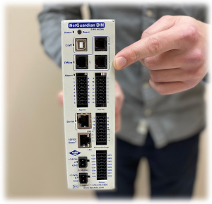
This integration is why our RTUs are designed to support both D-Wire sensor networks and traditional analog inputs (0-5 VDC and 4-20 mA), and to report via SNMP to a central alarm master. Our temperature and humidity sensors connect directly into this workflow. Temperature alarms from a remote shelter in Montana and server room hot-spot alerts from a central facility both flow into the same monitoring system.
Across a distributed network, that consolidation compounds. The sensor technology at each site matters less than whether every site's temperature alarms are visible in the same place.
Before committing to any sensor system, run through these five questions:
DPS Telecom has been engineering remote monitoring systems since 1986. If the 172,000+ devices we've deployed across telecom, utility, and infrastructure networks have taught us anything, it's that the questions in this guide come up on almost every project.
If you're evaluating temperature monitoring for an equipment room, remote shelter, or distributed site network, we're glad to help you work through the specifics (including which sensor interfaces fit your RTU platform and how to integrate environmental alarms with your SNMP-based NOC), contact us at dpstele.com/dps/contact.php or call 1-800-693-0351.

Andrew Erickson
Andrew Erickson is an Application Engineer at DPS Telecom, a manufacturer of semi-custom remote alarm monitoring systems based in Fresno, California. Andrew brings more than 19 years of experience building site monitoring solutions, developing intuitive user interfaces and documentation, and opt...