Check out our White Paper Series!
A complete library of helpful advice and survival guides for every aspect of system monitoring and control.
1-800-693-0351
Have a specific question? Ask our team of expert engineers and get a specific answer!
Sign up for the next DPS Factory Training!
Whether you're new to our equipment or you've used it for years, DPS factory training is the best way to get more from your monitoring.
Reserve Your Seat Today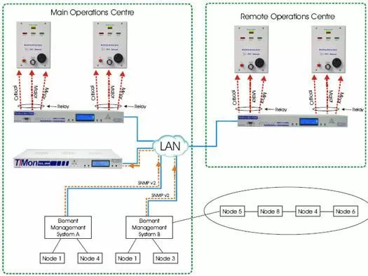
This application features an alarm panel solution to provide an audio and visual presentation of your major, minor, and critical alarms at your Main Operations Centre and the Remote Operations Centre. The equipment will allow you to collect alarm data from your Element Management Systems as SNMP v2 (v2c) traps over LAN and have those alarms displayed through the Building Status Unit's (minor, major or critical) LED's.
The Building Status Unit will provide Critical, Major and Minor visual indicators to reflect the alarm status of the BSU's location. Typically this would be located in break room or other any other location where you wish to notify people they should return to the monitoring console.
The BSU can be mounted near the door of a remote facility to provide personnela with a "last glance out the door" view of equipment status. In large facilities it can be used as an aisle status indicator. The BSU operates in conjunction with the NetGuardian G4's control relays. The BSU is controlled by relays in the NetGuardian G4 alarm remote. A relay is assigned to the critical, major and minor alarm levels. Relay operation causes the BSU to flash the appropriate visual indicator and sound the audible alarm. Pressing the ACK button changes the visual indicator to solid and silences the audible alarm.
The two visual indicators at the top of the BSU are controlled by a "sanity" pulse. The Sanity Indicator verifies that communications is functioning and the status indicated is current. Pulses must be received within a programmable time window for the green indicator to remain on. If pulses stop coming, the red indicator comes on to show that the display is not current.
An Alarm Cut Off (ACO) function is provided for silencing the audible alarm device. Pressing the ACK button three times activates the ACO. Pressing three times again deactivates the ACO. A green ON LINE indicator flashes when ACO is activated. Alarm volume can be set with a control on the BSU front panel.
Three severity indicators show system or site status and summarizes alarm status on one visual display and can be located at manager or remote sites. The visual and audible alarm indicator and sanity check indicator verifies proper operation ACK and ACO functions.